DNA-origami nanorulers
DNA-origami nanorulers are reference samples for super-resolution microscopy: a stiff DNA rod with marks placed on it
to nanometre accuracy, so that a microscope's image can be checked against a known distance
[scheckenbach2020]. inSiliScope's nanoruler sample is a field of such rods
lying flat on the coverslip, each carrying three spots of DNA-PAINT docking strands 80 nm apart (the spacing is
adjustable), or of flat 2D origami carrying a pattern of strands (the TU Delft logo). Mount it with the
viewer's Specimen select, Micro-Manager's SampleHolder (or the Specimen config group) or the CLI's
--specimen Nanorulers (Samples). The dyes, the light path, the PSF and the camera are the
same as for the cell field (Physics).
Each molecule goes through: the design at rest → which strands carry a dye (the label) → bending → landing (roll, height) → placement (position, direction). Every step is a pure function of the seed and the molecule's address, so any window of the field can be made alone, in any order, with the same result.
The designs
The designs live in data/origami/designs.json (Design). Their spots sit on a lattice whose step is the site
spacing (SpacingNm: 640, 320, 160, 80, 40, 20, 10 or 5 nm in the viewer and Micro-Manager, any value on the
CLI), and the molecule grows or shrinks with it.
1D origami: the nanoruler
Nanoruler:
- Body: a cylinder 13 nm in diameter, the typical nanoruler, a 12-helix bundle [scheckenbach2020] (p. 110902-3), reaching 20 nm beyond the outer spots: 2 × spacing + 40 nm long. At the default 80 nm that is the typical 200 nm rod.
- Spots: A, B and C one spacing apart, 20 nm from the ends: at 80 nm spacing at 20, 100 and 180 nm along the rod (80 nm from A to B and from B to C, 160 nm from A to C); at 40 nm at 20, 60 and 100 nm of a 120 nm rod. A longer rod bends more (below).
- Strands: each spot is a ring of 5 docking-strand positions, 72° apart around the rod (radius 6.5 nm). This is a
modelling choice, not a product's specification; no published strand count per spot was found.
StrandsPerSpot(1-5) keeps positions 1..N of each ring, the same subset on every rod.
2D origami: the TU Delft logo
TUDelftLogo: a flat single-layer sheet carrying the TU Delft logo (flame, T, U and D) as 37 cells of a 17 × 11 map
of flat-topped hexagons, one docking strand at the centre of each, neighbouring centres one spacing apart (columns
spacing × √3/2 apart, odd columns half a step down).
- Body: a rigid plate covering the whole hex map, about 15 × 11.5 spacings (1.2 × 0.92 µm at 80 nm, 300 × 230 nm
at 20 nm), 2 nm thick (about one DNA helix: estimate). It does not bend (
BendingandPersistenceLengthNmdo not apply). - Landing: always face up, so the logo is never mirrored; only its direction in the plane is random.
Rolldoes not apply. - Strands: one per cell, on the top face (
StrandsPerSpotis 1).
A new 2D design is a list of cell labels: the schema (lattice with cols, rows and cells as CCRR, column then
row from the top-left, as a hex-map editor numbers them) is described at the top of designs.json and in
Extending.
The spacing scales the rod and the logo alike:
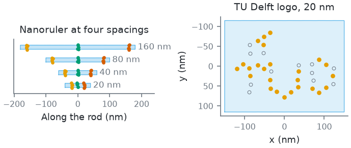
How this figure was made (5 cli runs, 14 ms)
Generated by tools/build_physics_figures.py (figure ruler-spacing) from the code it documents at commit 72b1b0f, on Linux with 4 threads, 2026-11-01. Commands, in order, with their wall time (those marked [served] ran one after the other in one insiliscope_cli --serve process, which keeps the world and the PSF kernel between commands; their outputs are the same as separate runs'):
insiliscope_cli --geometry-json rod160.geometry.json --x 0 --y 0 --specimen Nanorulers --geometry-um 4 --geometry-detail 1 --origami-spacing-nm 160 --origami-bend 0    # 4.7 ms [served]
insiliscope_cli --geometry-json rod80.geometry.json --x 0 --y 0 --specimen Nanorulers --geometry-um 4 --geometry-detail 1 --origami-spacing-nm 80 --origami-bend 0    # 2.0 ms [served]
insiliscope_cli --geometry-json rod40.geometry.json --x 0 --y 0 --specimen Nanorulers --geometry-um 4 --geometry-detail 1 --origami-spacing-nm 40 --origami-bend 0    # 1.9 ms [served]
insiliscope_cli --geometry-json rod20.geometry.json --x 0 --y 0 --specimen Nanorulers --geometry-um 4 --geometry-detail 1 --origami-spacing-nm 20 --origami-bend 0    # 1.9 ms [served]
insiliscope_cli --geometry-json logo20.geometry.json --x 0 --y 0 --specimen Nanorulers --geometry-um 4 --geometry-detail 1 --origami-design TUDelftLogo --origami-spacing-nm 20    # 3.1 ms [served]
The field
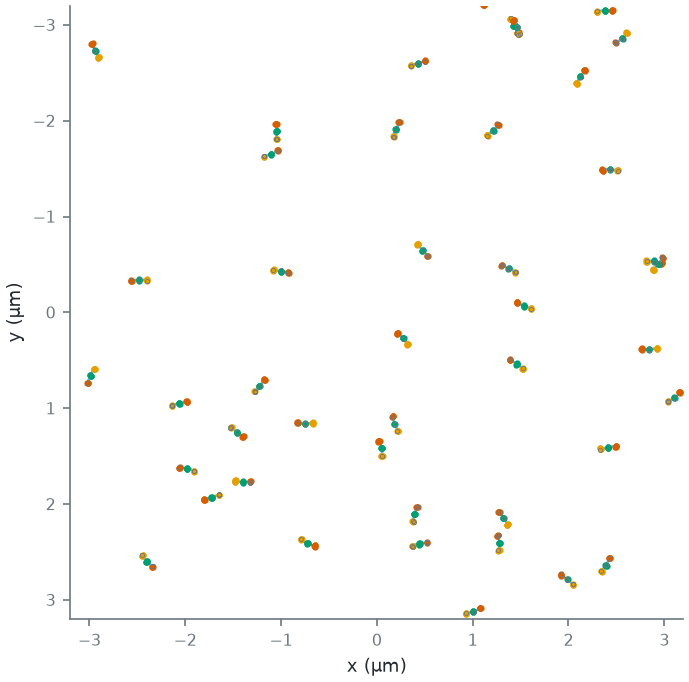
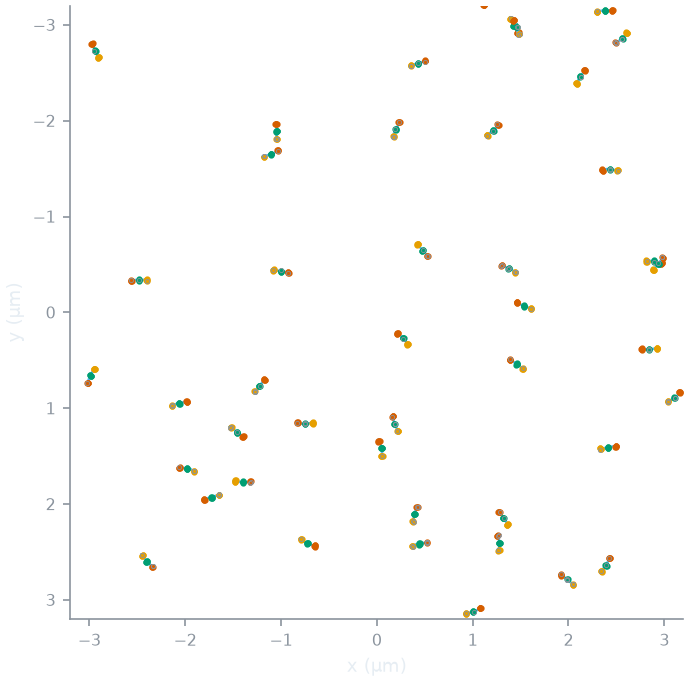
The coverslip is cut into 2 µm tiles. Each tile holds a Poisson number of candidate molecules (rods or plates; "rods" below) (mean = the density × 4
µm²; DensityPerUm2, default 1.2 µm⁻², estimate), each at a uniform position in the tile and a uniform direction.
By default the rods are placed independently (a Poisson field: they may touch or cross). A minimum spacing
(MinSpacingNm, default 0 = none) removes a candidate when a candidate of higher priority (a random number per
candidate) lies within it, looking across the neighbouring tiles too (Matérn type II thinning): the rods left are then
never closer than that, centre to centre, and the density after thinning is below the set one. The draws for the field are separate from those for the bending, so changing the
persistence length, the spacing or the design never moves or turns a rod.
Bending
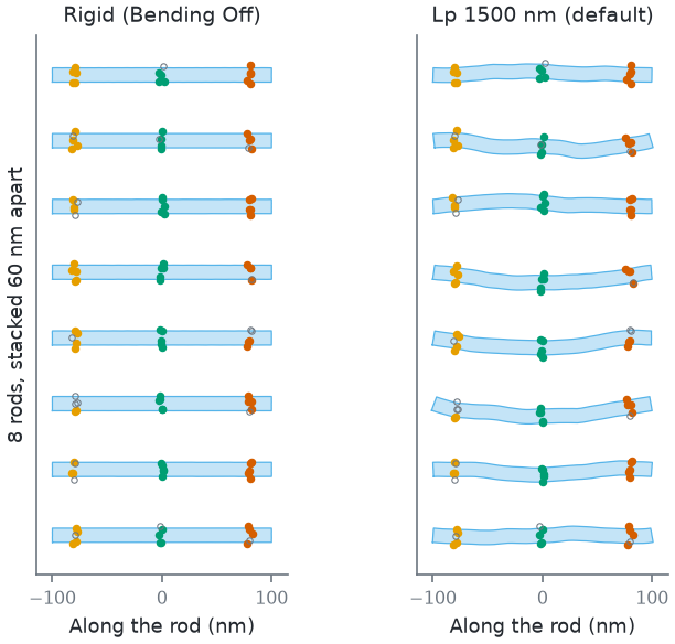
A rod lying on the glass bends within the plane. Its centreline is a two-dimensional worm-like chain: a chain that has equilibrated on the surface, as DNA can on a suitable one [rivetti1996]. The rod (L = 200 nm at the default spacing) is cut into \(n = \max\left(8, \lceil L / (D/2) \rceil\right) = 31\) segments of length \(\Delta s = L / n\). Segment j turns the direction by a normal angle step:
so the direction makes a random walk along the rod. Each segment is an exact circular arc of its own curvature, so the contour length stays L. Cross-sections stay straight and normal to the centreline: the 13 nm body is drawn around it, and a strand keeps its place along the rod and across it. The bent rod is then placed with the line between its ends along its direction and the middle of that line at its position. For this chain:
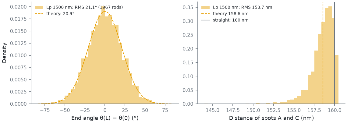
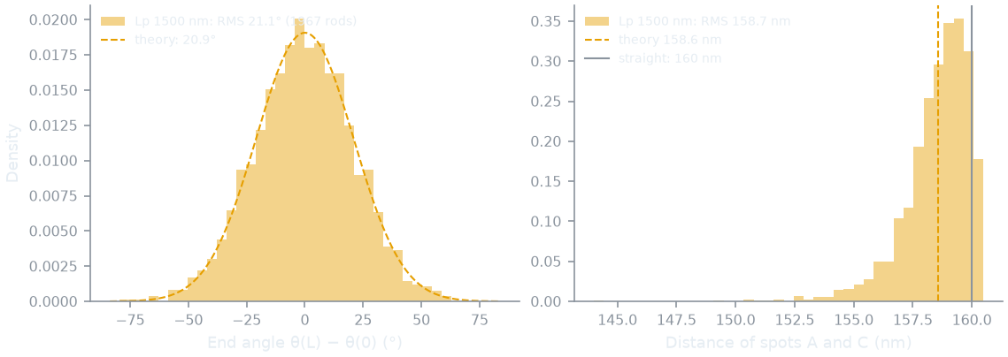
- the end tangents differ by a normal angle of variance L / Lp: 20.9° RMS at the default 1500 nm;
- the tangent correlation over a contour s is ⟨cos Δθ(s)⟩ = e−s / 2Lp (the 3D chain's e−s / Lp, with half the freedom to turn);
- so the mean square distance between two points s apart is the 3D chain's formula with Lp → 2Lp: ⟨R²⟩ = 4 Lp s [1 − (2Lp/s)(1 − e−s / 2Lp)].
The persistence length (PersistenceLengthNm, Advanced, default 1500 nm, an estimate). Measured bending
persistence lengths of DNA-origami helix bundles are 740 nm to 1 µm for four-helix, 1-3 µm for six-helix and 3-8.2 µm
for eight-helix bundles [chhabra2020] (their summary of the measurements, p. 4 of
the arXiv version; simulations give somewhat higher values). A 12-helix rod is stiffer still, so 1500 nm leans to the
soft side. Bending Off makes every rod straight.
How this figure was made (2 cli runs, 10 ms)
Generated by tools/build_physics_figures.py (figure ruler-shapes) from the code it documents at commit 72b1b0f, on Linux with 4 threads, 2026-11-01. Commands, in order, with their wall time (those marked [served] ran one after the other in one insiliscope_cli --serve process, which keeps the world and the PSF kernel between commands; their outputs are the same as separate runs'):
insiliscope_cli --geometry-json rigid.geometry.json --x 0 --y 0 --specimen Nanorulers --geometry-um 6 --geometry-detail 1 --origami-bend 0    # 6.1 ms [served]
insiliscope_cli --geometry-json lp1500.geometry.json --x 0 --y 0 --specimen Nanorulers --geometry-um 6 --geometry-detail 1    # 3.9 ms [served]
How far bending moves the spots: the outer spots, 160 nm apart along the rod, are 158.6 nm apart (RMS, the formula above) at 1500 nm; bending can only bring them closer.
How this figure was made (1 cli run, 183 ms)
Generated by tools/build_physics_figures.py (figure ruler-wlc) from the code it documents at commit 72b1b0f, on Linux with 4 threads, 2026-11-01. Commands, in order, with their wall time (those marked [served] ran one after the other in one insiliscope_cli --serve process, which keeps the world and the PSF kernel between commands; their outputs are the same as separate runs'):
insiliscope_cli --geometry-json lp1500.geometry.json --x 0 --y 0 --specimen Nanorulers --geometry-um 40 --geometry-detail 1 # 183 ms [served]
A bend sharper than the half-width of the rod (curvature × 6.5 nm ≥ 1) would fold a cross-section over itself; such
rods are counted (the geometry output's fold) but kept. None occur at the default persistence length.
Landing and heights
Each rod lands rolled about its own axis: a uniform random roll per rod (Roll = Uniform), or one fixed angle for
all (Fixed, RollDeg). The roll turns each spot's ring of strands, so seen from above the strands of a spot lie at
different places across the rod. The rod's bottom is AttachHeightNm (7 nm, estimate: the surface coating) above
the glass.
The sample is two-dimensional (v1): every strand sits at the height of the rod's axis, 7 + 6.5 = 13.5 nm above the
coverslip. KeepHeights (Expert) puts each strand at its ring height around the rod instead (from 7 to 20 nm), a first
step towards 3D designs, not validated yet.
The label
The docking strands are the sample's one target (docking, options ruler-*, Micro-Manager Nanorulers.Docking_*).
They take a label like the cell field's microtubules: a dye of the library in a mode
(Dyes and light path).
- Typical labels (
data/dyes/library.jsontypicalLabels.docking): an ATTO 655 imager in DNA-PAINT (the default), AF647 in dSTORM, mEos3.2 in PALM, ATTO 655 in WideField; the dye of a non-PAINT mode stands for a dye attached to the strand. - Labelled % (
Docking_LabelingPct, 80 %, estimate): the share of designed strands that were incorporated and carry a dye, drawn independently per strand. - Linker (
LinkerNm, 3 nm, estimate): each dye lies at a random point within this distance of its strand's anchor, on the outer side. - DNA-PAINT: each strand binds imagers at kon × c, with c the imager concentration in the buffer
(
Docking_ImagerNanoMol, Advanced, 20 nM by default: the setting for how dense the frames are), and the free imager adds a uniform background (photophysics). The binding kinetics are the docking strands' (data/specimens.jsonpaint), not the dye's: kon 10⁶ M⁻¹ s⁻¹ (KonPerMolarPerSec) and a bound half-time of 200 ms (mean 0.289 s,BoundTimeSec), both estimates (9 nt docking strands bind for about 0.3-1 s). A rod with 12 labelled strands then binds an imager about every 80 s per nM: every ~4 s at the default 20 nM, each binding lasting a few frames, so a field of view shows a few rods binding per frame over the free imager's background. Lower the concentration for sparser frames and less background; take thousands of frames, as in a real DNA-PAINT experiment.
How this figure was made (1 cli run, 10 ms)
Generated by tools/build_physics_figures.py (figure ruler-field) from the code it documents at commit 72b1b0f, on Linux with 4 threads, 2026-11-01. Commands, in order, with their wall time (those marked [served] ran one after the other in one insiliscope_cli --serve process, which keeps the world and the PSF kernel between commands; their outputs are the same as separate runs'):
insiliscope_cli --geometry-json fov.geometry.json --x 0 --y 0 --specimen Nanorulers --geometry-um 6.4 --geometry-detail 1 # 10 ms [served]
Parameters
| Viewer | Micro-Manager | CLI | Default | Source |
|---|---|---|---|---|
| Specimen | SampleHolder |
--specimen |
CellField | |
| Design | Nanorulers.Design |
--origami-design |
Nanoruler | [scheckenbach2020] (body) |
| Site spacing | Nanorulers.SpacingNm |
--origami-spacing-nm |
80 nm | |
| Density | Nanorulers.DensityPerUm2 |
--origami-density |
1.2 µm⁻² | estimate |
| Strands per spot | Nanorulers.StrandsPerSpot |
--origami-strands-per-spot |
5 | modelling choice |
| Bending | Nanorulers.Bending |
--origami-bend |
On | |
| Persistence length | Nanorulers.PersistenceLengthNm |
--origami-lp-nm |
1500 nm | estimate, [chhabra2020] (range) |
| Min spacing | Nanorulers.MinSpacingNm |
--origami-min-spacing-nm |
0 (none) | |
| Height above glass | Nanorulers.AttachHeightNm |
--origami-attach-nm |
7 nm | estimate |
| Linker | Nanorulers.LinkerNm |
--origami-linker-nm |
3 nm | estimate |
| Roll, roll angle | Nanorulers.Roll, RollDeg |
--origami-roll, --origami-roll-deg |
Uniform, 0° | |
| 3D strand heights | Nanorulers.KeepHeights |
--origami-heights |
Off | |
| Docking strands label | Nanorulers.Docking_Label, _Mode, _LabelingPct, _ImagerNanoMol |
--ruler-dye, --ruler-mode, --ruler-label-pct, --ruler-imager-nm |
Typical (ATTO 655 DNA-PAINT), 80 %, 20 nM | estimates |
| DNA-PAINT binding | Nanorulers.Docking_BoundTimeSec, _KonPerMolarPerSec |
--ruler-paint-on-sec, --ruler-paint-kon |
0.289 s (half-time 200 ms), 10⁶ M⁻¹s⁻¹ | estimates |
The core parameters are the origami* names (origamiLpNm, ...; p.<name> on the CLI). The CLI's --geometry-json
lists each molecule in a window (position, direction, roll, end angle, fold, the bent outline and, with
--geometry-detail 1, every strand: spot, ring position, world position, straight and bent position in the
molecule's frame, labelled or not); the figures on this page are made from it.
Limits
- Two-dimensional: the molecules lie flat, the strands at one height; no 3D designs yet. 2D origami land face up only (a sheet that lands face down would show its pattern mirrored, with the strands under it).
- Every rod is whole: no broken rods, missing spots or misfolded molecules beyond the labelled %.
- Uniform stiffness, no built-in curvature; rods may touch or cross (a minimum spacing thins them by their centres only).
- Bodies: a cylinder with in-plane bending (or none) and a uniform or fixed roll, and a rigid plate with a hex map of strands.
- No BrightField contrast (see Samples).
- The viewer draws the rods in its map; its animation exports do not include them yet.