Dyes and light path
Since issue 16 every structure carries a label: a dye of the library in one of four modes, imaged through a light path of lasers, a dichroic, an emission filter and the camera's QE curve. What a dye emits, at which wavelength (and so with which PSF), and how fast it switches all follow from the dye's data and the light path; nothing is a free "photons per second" number any more. Only the microtubules carry a label today. The switching models themselves are on Photophysics.
The dye library
data/dyes/library.json holds the dyes and fluorescent proteins: AF647, AF532, Cy5, ATTO 655, ATTO 542, mEos3.2,
Dendra2, PAmCherry2, mEGFP, mScarlet, DAPI, Hoechst 33342 and a Custom dye with Gaussian spectra. Spectra, extinction
coefficients and quantum yields come from FPbase [lambert2019] (CC BY-SA 4.0); per-mode
kinetics come from the literature named in each entry (dSTORM from [dempsey2011],
DNA-PAINT from [jungmann2010, schnitzbauer2017],
PALM photoactivation efficiencies from [durisic2014], primed conversion from
[dempsey2015, turkowyd2017]). Values without a
measurement behind them are marked estimate in the data. References lists every source.
A dye has a default mode and a block per mode it supports. The fluorescent fraction (e.g. the share of a PALM protein that ever photoactivates) thins the labelled sites with its own address-based draw, nested in the labelled set.
Three dye slots (dye1..3.source, MM Fluorophores.Dye{1,2,3}_Source) hold edited copies of library dyes; a structure
can use a slot (mt-dye=Dye1). Any dye field can be overridden per structure (mt-dye.on-sec=0.03) or per slot
(dye1.qy=0.5). Micro-Manager shows the slots as Fluorophores.Dye<N>_* (Expert), loaded from the library when their
source changes and editable after; a structure there takes a slot (CellField.Microtubules_Label = Dye1) instead of
per-structure overrides.
Label modes
| Mode | Emitters | Rendered as |
|---|---|---|
| dSTORM | an initial ON phase (all dyes on, Exp(initial-on-sec)), then blinks until bleached |
blinks; the initial ON as a continuous population |
| PALM | optional pre-converted state (e.g. mEos3.2 green) until activation, then blinks | blinks; the pre state as a continuous population |
| DNA-PAINT | persistent binding sites: imager binds at \(k_{on} c\), never bleaches (\(k_{on}\) and the bound time are the target's: photophysics) | blinks, plus the free imager's background |
| WideField | every dye emits from \(t=0\) and bleaches by its photon budget | a continuous population |
Changing the mode sets the labelled share of the binding sites to the mode's suggestion (DNA-PAINT 70 %, dSTORM 3 %, PALM 25 %, WideField 70 %; estimates of typical densities), as the viewer does.
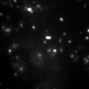
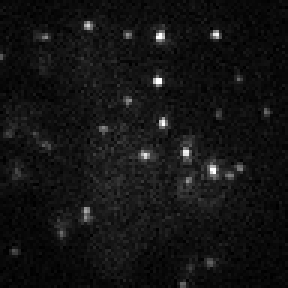
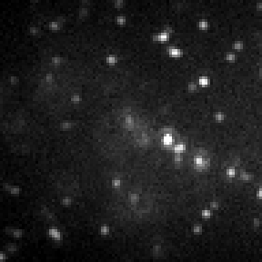
The four modes on one field:
| dSTORM Alexa Fluor 647, 3 % |
PALM mEos3.2, 25 % |
DNA-PAINT ATTO 655, 70 % |
WideField mEGFP, 70 % |
|---|---|---|---|
 |
 |
 |
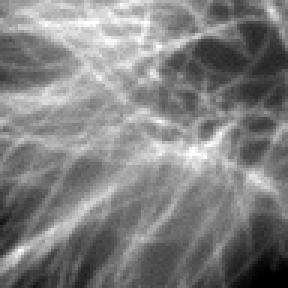 |
One camera frame of the same 9.6 µm field (96 px of 100 nm, 50 ms, t = 60 s) with each mode's typical label, labelled share and light preset, each with its own contrast. The blinking modes show a few emitters per frame and the structure only over many frames; WideField shows it in every frame.
How this figure was made (4 cli runs, 5.66 s)
Generated by tools/build_physics_figures.py (figure light-modes) from the code it documents at commit 72b1b0f, on Linux with 4 threads, 2026-11-01. Commands, in order, with their wall time (those marked [served] ran one after the other in one insiliscope_cli --serve process, which keeps the world and the PSF kernel between commands; their outputs are the same as separate runs'):
insiliscope_cli --out dSTORM.movie.tif --setup-json dSTORM.setup.json --x 6.58 --y -5.61 --size 96 --frames 1 --mt-mode dSTORM --mt-dye -1 --light-preset auto --npc-dye None    # 977 ms [served]
insiliscope_cli --out PALM.movie.tif --setup-json PALM.setup.json --x 6.58 --y -5.61 --size 96 --frames 1 --mt-mode PALM --mt-dye -1 --light-preset auto --npc-dye None    # 1.10 s [served]
insiliscope_cli --out DNA-PAINT.movie.tif --setup-json DNA-PAINT.setup.json --x 6.58 --y -5.61 --size 96 --frames 1 --mt-mode DNA-PAINT --mt-dye -1 --light-preset auto --npc-dye None    # 2.30 s [served]
insiliscope_cli --out WideField.movie.tif --setup-json WideField.setup.json --x 6.58 --y -5.61 --size 96 --frames 1 --mt-mode WideField --mt-dye -1 --light-preset auto --npc-dye None    # 1.28 s [served]
Excitation, emission and detection
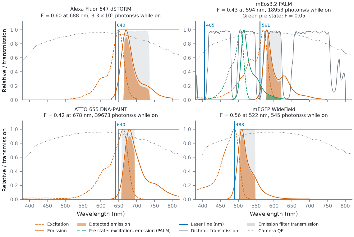
For each dye state (main, or a PALM pre state) and the light path:
with \(\varepsilon\) the extinction coefficient, \(E\) the normalised excitation spectrum, \(\Phi\) the laser's photon flux (from its intensity in kW/cm\(^2\)) and \(T_D\) the dichroic's transmission (a long-pass reflects the laser onto the sample). \(\sigma\) is the Beer-Lambert cross-section: \(10^{-\varepsilon c l} = e^{-\sigma n l}\) with \(n = 10^{-3} c N_A\) molecules per cm\(^3\) for \(c\) in mol/L. The emission rate is \(k_{em} = \mathrm{QY}\,k_{exc}\). The detected fraction of the emission spectrum \(S\) is
through the dichroic, the emission filter \(T_F\) and the camera's QE curve, and the detected photons per second while
emitting are \(k_{em}\,\eta\,F\) with the objective's collection efficiency
\(\eta = \tfrac12\bigl(1 - \sqrt{1 - (\mathrm{NA}/n)^2}\bigr)\), the share of isotropic emission inside the objective's
cone (\(\sin\theta = \mathrm{NA}/n\)). The PSF of each state is computed at the detected-spectrum-weighted wavelength,
rounded to 2 nm (one kernel per distinct wavelength). MM shows the microtubules' main state as read-only properties: Fluorophores.Microtubules_DetectedPct (\(100F\), without \(\eta\)),
EffectiveEmissionNm and PhotonsPerSecOn (\(k_{em}\eta F\)).
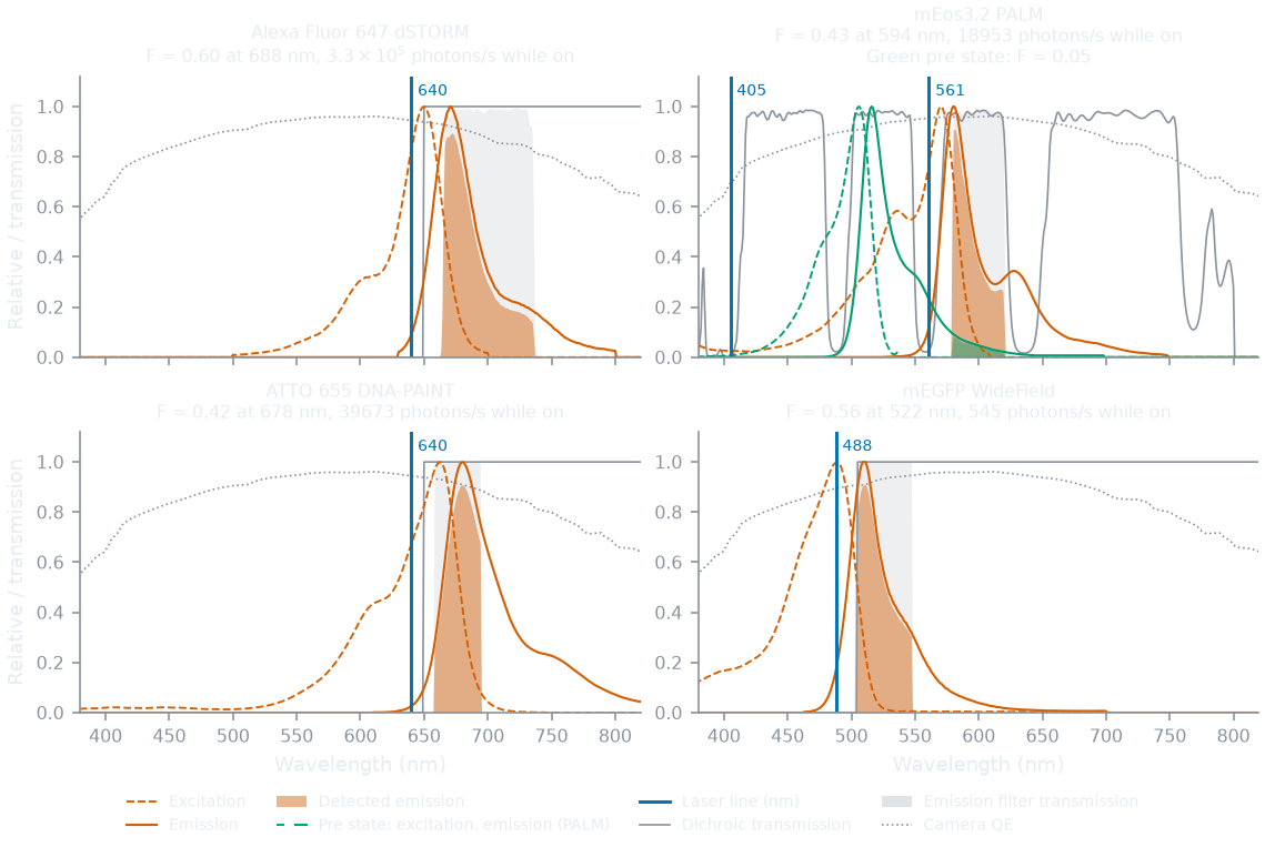
The four typical labels through their light presets, as a movie resolves them:
How this figure was made (4 cli runs, 45 ms)
Generated by tools/build_physics_figures.py (figure light-spectra) from the code it documents at commit 72b1b0f, on Linux with 4 threads, 2026-11-01. Commands, in order, with their wall time (those marked [served] ran one after the other in one insiliscope_cli --serve process, which keeps the world and the PSF kernel between commands; their outputs are the same as separate runs'):
insiliscope_cli --setup-json dSTORM.setup.json --mt-mode dSTORM --mt-dye -1 --light-preset auto --npc-dye None    # 15 ms [served]
insiliscope_cli --setup-json PALM.setup.json --mt-mode PALM --mt-dye -1 --light-preset auto --npc-dye None    # 11 ms [served]
insiliscope_cli --setup-json DNA-PAINT.setup.json --mt-mode DNA-PAINT --mt-dye -1 --light-preset auto --npc-dye None    # 8.6 ms [served]
insiliscope_cli --setup-json WideField.setup.json --mt-mode WideField --mt-dye -1 --light-preset auto --npc-dye None    # 11 ms [served]
Because the QE is in \(F\), the camera noise chain runs at QE 1 for fluorescence; the flat background-per-sec is
multiplied by the QE at the filter's centre. BrightField uses the curve's QE at its lamp wavelength.
Activation and switching rates follow the lasers too: dSTORM switches on at \(1/\tau_{off} + a_{405} I_{405}\), and
its ON, spontaneous-dark and initial-ON times scale as \(k_{exc,ref}/k_{exc}\), so the photons per blink and the duty
cycle stay as measured at Dempsey et al.'s intensities (488 nm 1.2, 561 nm 2.2, 647 nm 0.8 kW/cm\(^2\))
[dempsey2011] (\(a_{405}\) set from the 405 nm sensitivity grades of its Table 2). PALM
activates at the spontaneous rate plus \(a_{405} I_{405}\) plus, for primed conversion, a term in the product of the
470-510 nm and 690-780 nm intensities [dempsey2015,
turkowyd2017] (the PALM rate coefficients are estimates). DNA-PAINT blinks at
\(k_{on} c\) [jungmann2010] (\(k_{on}\) of the order of \(10^6\) /M/s, an estimate),
with \(c\) the imager concentration (mt-imager-nm, MM CellField.Microtubules_ImagerNanoMol).
Light-path presets
data/dyes/light_path.json defines the lasers (405, 488, 561, 640, 730 nm and a custom line), dichroics, emission
filters and presets: dSTORM-640/561/488 (Dempsey's conditions [dempsey2011]),
PAINT-640/561/488, PALM-561, PALM-primed, WF-405/488/561/640, and the samples' own: Beads-561 (the bead
sample) and Slide-405/488/561/640 (the fluorescent slide: a line at 0.02 kW/cm² with the WF
preset's filters). Intensities without a source are estimates.
Every dye mode names its preset. light-preset=auto (the default, cli/viewer; MM Lasers.Preset Auto) combines
the presets of the labelled targets of the mounted sample: each laser at its largest power among them, the dichroic and
filter where they all agree, else a multi-band set (Chroma ZT405/488/561/640rpc dichroic and ZET405/488/561/640m
emission filter, FPbase curves [lambert2019]), so one image shows every target with
its real cross-talk. A dye or mode change re-applies it (viewer, MM). With one labelled target that is its own preset,
e.g. PAINT-640 (640 nm at 1 kW/cm\(^2\), an estimate; LP650, 676/37) for the microtubules' ATTO 655 DNA-PAINT
label alone. The default cell field labels two targets: the microtubules (ATTO 655, PAINT-640) and the nuclear
pores (Cy3B, PAINT-561), so 561 and 640 nm through the multi-band set. Camera presets
(cameras.json: Kinetix22, iXon Ultra 897, ...) set the noise values and the QE curve.
Excitation (laser clean-up) filters
An excitation filter sits between the lasers and the dichroic (ex-filter, MM ExcitationFilter wheel or the
FilterCube). Each laser line's intensity is multiplied by the filter's transmission at that line, so a 640 nm
clean-up blocks the 561 nm line, as on a real scope. The library has None (the default, and every preset's),
ideal laser-line band passes of +/- 5 nm (BP405-10, BP488-10, BP561-10, BP640-10), an ideal quad (Quad),
measured curves from FPbase [lambert2019] of Chroma ZET405/20x, ZET488/10x,
ZET561/10x, ZET642/20x and the quad ZET405/488/561/640xv2, and Semrock FF01-405/10, FF01-488/10, FF01-561/14 and
FF01-640/14, and a Custom band pass (ex-lo-nm, ex-hi-nm). Semrock's MaxDiode/MaxLine clean-ups (LD01-405/10,
LL02-561, ...) have no FPbase curve; the FF01 band passes stand in for them.
Which light: the shutters
The lasers (epi) and the transmitted lamp each have a shutter: light-epi and light-trans (1 open, 0 closed;
-1, the default, follows modality: Fluorescence opens the lasers, BrightField the lamp). In Micro-Manager they
are the Lasers and TransmittedLamp shutter devices. Lasers alone give the fluorescence image, the lamp alone the
BrightField image. Both open add up on one camera: the fluorescence photons plus the lamp's photons times the
camera's QE at the lamp wavelength, then one noise chain (so the lamp's shot noise sits on the fluorescence, as it
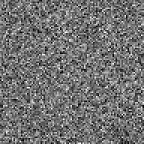
would on a real scope). None open gives dark frames: offset, read noise and dark current only.
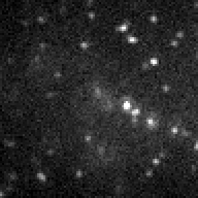
| Lasers (epi) | Lamp (transmitted) | Both | None | |
|---|---|---|---|---|
| Frame | 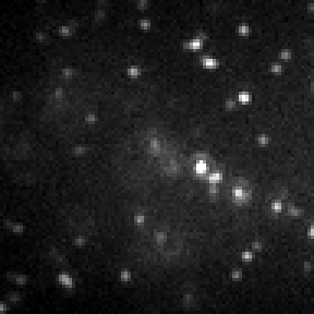 |
 |
 |
 |
| Median (ADU) | 375 | 1050 | 1325 | 100 |
The two shutters (cli light-epi, light-trans; Micro-Manager's Lasers and TransmittedLamp) with the default label (ATTO 655 DNA-PAINT) and the lamp turned down to 5000 photons/px/s so both lights show. Both open: the fluorescence photons plus the lamp's, through one noise chain. None: offset, read noise and dark current only. Each image has its own contrast.
How this figure was made (4 cli runs, 1.82 s)
Generated by tools/build_physics_figures.py (figure light-shutters) from the code it documents at commit 72b1b0f, on Linux with 4 threads, 2026-11-01. Commands, in order, with their wall time (those marked [served] ran one after the other in one insiliscope_cli --serve process, which keeps the world and the PSF kernel between commands; their outputs are the same as separate runs'):
insiliscope_cli --out lasers.movie.tif --x 6.58 --y -5.61 --size 96 --frames 1 --light-epi 1 --light-trans 0 --bf-photons-per-px-per-sec 5000 --npc-dye None    # 1.62 s [served]
insiliscope_cli --out lamp.movie.tif --x 6.58 --y -5.61 --size 96 --frames 1 --light-epi 0 --light-trans 1 --bf-photons-per-px-per-sec 5000 --npc-dye None    # 153 ms [served]
insiliscope_cli --out both.movie.tif --x 6.58 --y -5.61 --size 96 --frames 1 --light-epi 1 --light-trans 1 --bf-photons-per-px-per-sec 5000 --npc-dye None    # 41 ms [served]
insiliscope_cli --out none.movie.tif --x 6.58 --y -5.61 --size 96 --frames 1 --light-epi 0 --light-trans 0 --bf-photons-per-px-per-sec 5000 --npc-dye None    # 3.8 ms [served]
Illumination geometry
One number moves the laser spot across the objective's back focal plane (illum-bfp, MM Lasers.BfpPosition, the
shipped configs' Illumination group: Epi / HILO / TIRF): 0 is the centre (epi: the beam goes straight up), 1 the
critical angle, between them HILO (a highly inclined sheet, [tokunaga2008]) and
above it TIRF (an evanescent layer over the coverslip,
[axelrod1981], [axelrod2001]), up to the pupil edge
NA / n of the medium (1.047 for the 1.40 objective in water, n = bf-n-medium, MM SampleHolder.MediumIndex, 1.337);
beyond it no light reaches the sample (MM Lasers.IlluminationRegime reads Clipped). The position is linear in the
BFP radius, so 0.5 is half-way to the critical angle.
The beam's cross-section is illum-profile (Flat, Gaussian, the default, or FlatTop: a disc with a soft edge) with
illum-fwhm (% of the FOV width, default 100: the default Gaussian gives the middle of each edge half the centre's
light and the corners a quarter). Each dye is excited by the laser power times a factor at its place:
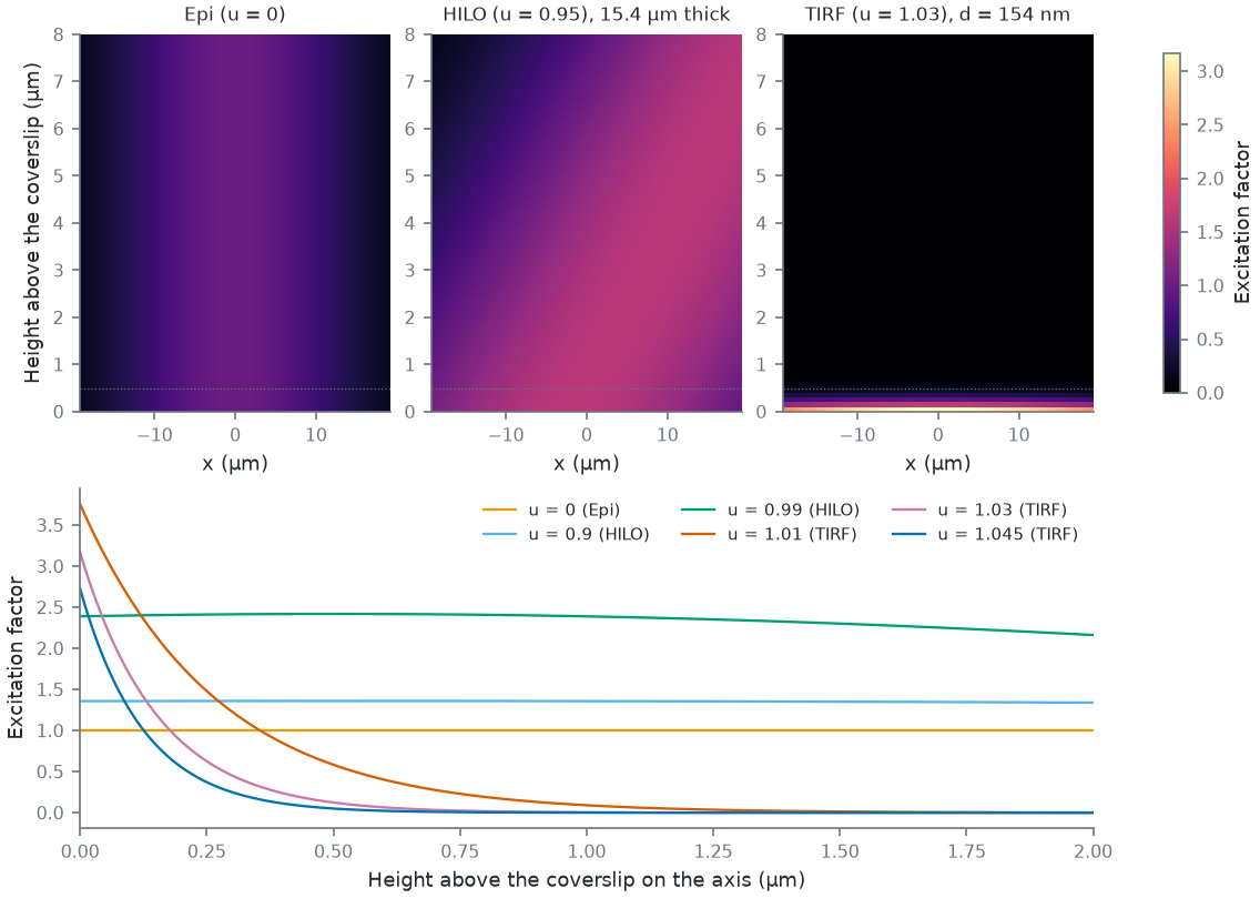
- epi: the profile, the same at every height;
- HILO: the profile tilted into a sheet through the focal plane, about W / (tan θs cos θi)
thick on the axis (W the beam's FWHM; at 0.95 about 0.6 W: 15 µm for the default beam over a 25.6 µm field, so
narrow the beam,
illum-fwhm, for a thin sheet; MMLasers.IlluminationDepthNm), dyes above or below it unlit; - TIRF: the profile at the coverslip times \(e^{-z/d}\), \(d = \lambda / (4\pi n \sqrt{u^2-1})\) (about 150 nm at 1.03 and 640 nm), with the interface's field enhancement (up to ~4x near the critical angle).
The factor changes the photons, and through the local light the kinetics: dSTORM switching, PALM activation and
bleaching run at the local excitation, each dye at the dose its own place and height has had
(Illumination history; a cli or viewer movie's past is
start-sec at its own light), so a TIRF field bleaches its bottom layer and leaves the dyes higher up fresh.
The DNA-PAINT light presets set HILO (0.95), the nanorulers TIRF (1.03), the other presets epi (all estimates); with
several labelled targets (light-preset auto) the position their presets agree on, else epi.
Supercritical-angle emission and the beam's angular spread in the BFP are not modelled. The physics in full:
spec/ALGORITHM.md, "Excitation geometry".
The excitation factor a movie applies, in a section through the axis and on the axis:
How this figure was made (9 cli runs, 148 ms)
Generated by tools/build_physics_figures.py (figure light-geometry) from the code it documents at commit 72b1b0f, on Linux with 4 threads, 2026-11-01. Commands, in order, with their wall time (those marked [served] ran one after the other in one insiliscope_cli --serve process, which keeps the world and the PSF kernel between commands; their outputs are the same as separate runs'):
insiliscope_cli --setup-json bfp0.setup.json --x 6.58 --y -5.61 --size 256 --frames 1 --illum-bfp 0 --npc-dye None    # 24 ms [served]
insiliscope_cli --setup-json bfp0.95.setup.json --x 6.58 --y -5.61 --size 256 --frames 1 --illum-bfp 0.95 --npc-dye None    # 21 ms [served]
insiliscope_cli --setup-json bfp1.03.setup.json --x 6.58 --y -5.61 --size 256 --frames 1 --illum-bfp 1.03 --npc-dye None    # 28 ms [served]
insiliscope_cli --setup-json bfp0.setup.json --x 6.58 --y -5.61 --size 256 --frames 1 --illum-bfp 0 --npc-dye None    # 23 ms [served]
insiliscope_cli --setup-json bfp0.9.setup.json --x 6.58 --y -5.61 --size 256 --frames 1 --illum-bfp 0.9 --npc-dye None    # 10 ms [served]
insiliscope_cli --setup-json bfp0.99.setup.json --x 6.58 --y -5.61 --size 256 --frames 1 --illum-bfp 0.99 --npc-dye None    # 10 ms [served]
insiliscope_cli --setup-json bfp1.01.setup.json --x 6.58 --y -5.61 --size 256 --frames 1 --illum-bfp 1.01 --npc-dye None    # 12 ms [served]
insiliscope_cli --setup-json bfp1.03.setup.json --x 6.58 --y -5.61 --size 256 --frames 1 --illum-bfp 1.03 --npc-dye None    # 12 ms [served]
insiliscope_cli --setup-json bfp1.045.setup.json --x 6.58 --y -5.61 --size 256 --frames 1 --illum-bfp 1.045 --npc-dye None    # 7.7 ms [served]
What it does to a frame, with the free DNA-PAINT imager's background:
| Epi (0) | HILO (0.95) | TIRF (1.03) | |
|---|---|---|---|
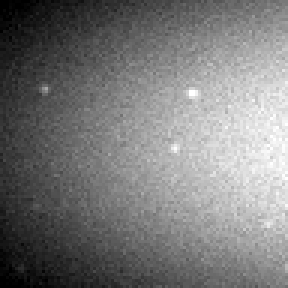
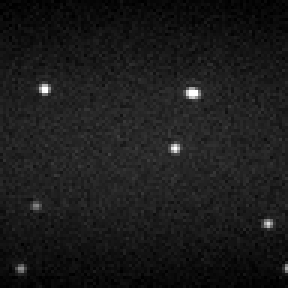
| Nanorulers | 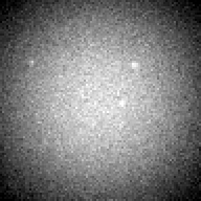 |
 |
 |
| Median (photons/px) | 1056 | 858 | 94.0 |
| Cell field | 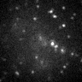 |
 |
 |
| Median (photons/px) | 67.9 | 68.8 | 5.00 |
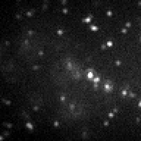
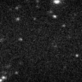
One frame (50 ms, 9.6 µm field, t = 60 s, each its own contrast) of the DNA-origami nanorulers (strands 13.5 nm over the coverslip, focus on them) and of the default cell field (focus 0.5 µm), both in DNA-PAINT, at three BFP positions. The median is the photon image before the camera, mostly the free imager: TIRF lights only the layer over the coverslip, so the nanorulers' background drops about ninefold. HILO's sheet is the beam's width over tan θs cos θi thick, here (a 9.6 µm beam) about 6 µm: about the column epi collects from a beam this narrow, so it changes little; its gain is against a wide epi beam. In the cell field TIRF leaves the microtubules above the evanescent layer dark.
How this figure was made (6 cli runs, 1.30 s)
Generated by tools/build_physics_figures.py (figure light-geometry-images) from the code it documents at commit 72b1b0f, on Linux with 4 threads, 2026-11-01. Commands, in order, with their wall time (those marked [served] ran one after the other in one insiliscope_cli --serve process, which keeps the world and the PSF kernel between commands; their outputs are the same as separate runs'):
insiliscope_cli --out Nanorulers-Epi.movie.tif --photons-out Nanorulers-Epi.photons.tif --setup-json Nanorulers-Epi.setup.json --x 6.58 --y -5.61 --size 96 --frames 1 --specimen 1 --illum-bfp 0    # 538 ms [served]
insiliscope_cli --out Nanorulers-HILO.movie.tif --photons-out Nanorulers-HILO.photons.tif --setup-json Nanorulers-HILO.setup.json --x 6.58 --y -5.61 --size 96 --frames 1 --specimen 1 --illum-bfp 0.95    # 29 ms [served]
insiliscope_cli --out Nanorulers-TIRF.movie.tif --photons-out Nanorulers-TIRF.photons.tif --setup-json Nanorulers-TIRF.setup.json --x 6.58 --y -5.61 --size 96 --frames 1 --specimen 1 --illum-bfp 1.03    # 30 ms [served]
insiliscope_cli --out Cell-Epi.movie.tif --photons-out Cell-Epi.photons.tif --setup-json Cell-Epi.setup.json --x 6.58 --y -5.61 --size 96 --frames 1 --illum-bfp 0 --npc-dye None    # 606 ms [served]
insiliscope_cli --out Cell-HILO.movie.tif --photons-out Cell-HILO.photons.tif --setup-json Cell-HILO.setup.json --x 6.58 --y -5.61 --size 96 --frames 1 --illum-bfp 0.95 --npc-dye None    # 60 ms [served]
insiliscope_cli --out Cell-TIRF.movie.tif --photons-out Cell-TIRF.photons.tif --setup-json Cell-TIRF.setup.json --x 6.58 --y -5.61 --size 96 --frames 1 --illum-bfp 1.03 --npc-dye None    # 33 ms [served]
Structured illumination (SIM)
The light can also be several coherent beams, each a spot in the objective's back focal plane, interfering in the
sample to a fringe pattern that steps with the frame (sim-type, MM Lasers.Pattern; the physics in full:
spec/ALGORITHM.md, "Structured illumination"):
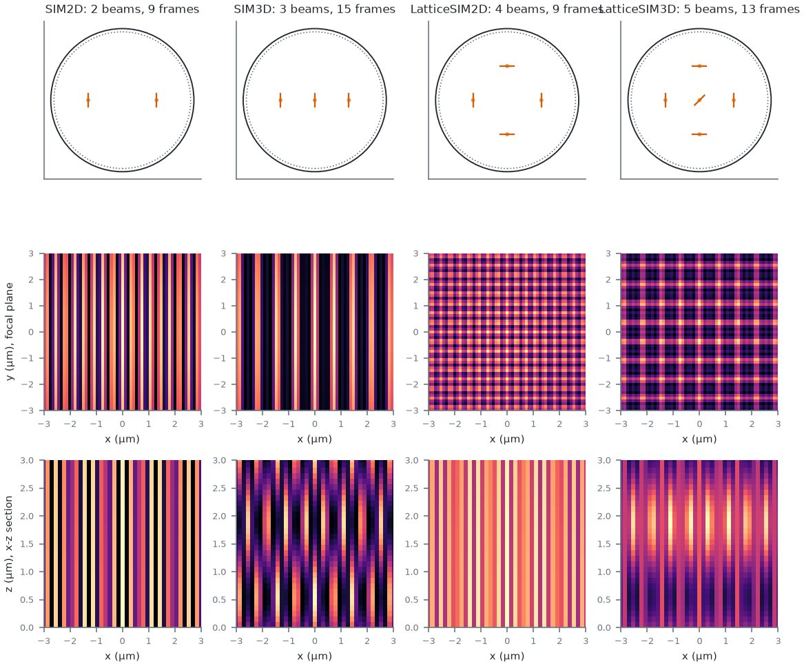
| type | beams | frames per cycle | after |
|---|---|---|---|
SIM2D |
two at ±r | 3 phases × 3 orientations (60° apart) | [gustafsson2000] |
SIM3D |
two at ±r and the centre | 5 phases × 3 orientations | [gustafsson2008] |
LatticeSIM2D |
±x and ±y | 9 phases, one orientation | a four-beam lattice |
LatticeSIM3D |
±x, ±y and the centre | 13 phases (the x and y pairs stepping 2 : 3) | the five-beam lattice of Zeiss's Lattice SIM |
Custom |
the beam matrix alone | sim-phases × sim-angles |
The beams sit at radius r = illum-bfp in the pupil: the BFP slider is the beams' radius, so past 1 the beams are
evanescent and the pattern is TIRF-SIM [kner2009]; a type pick sets it to the type's
default (2D 0.95, 3D and the lattices 0.9; estimates). Two beams at ±u make a fringe of period λ / (2 n u) in the
medium (180 nm at u = 0.95 and 640 nm): near the resolution limit, so the raw frames show little of the fringe itself
and mostly its moiré with the sample, which is what a reconstruction uses. Every beam's field is the single beam's
physics above at the beam's own angle (the Fresnel amplitudes below the critical angle, Axelrod's evanescent field
components with their phases above it [axelrod1984]), the pattern their coherent sum
squared [frohn2001]; the polarization (sim-polarization, Advanced) is S for every
type unless changed (each beam linearly polarized across its plane of incidence, a beam and its opposite with the
same field direction as one grating's +1 and -1 orders have: full fringe contrast, and the centre-beam fringes of
SIM3D at their maximum in the in-phase plane; for the lattice
the x and y pairs then do not interfere, and LatticeSIM3D's centre beam is linear diagonal under S and P,
interfering with both pairs alike and in phase, so both first-order fringes peak in the focal plane together; a
circular centre beam, set through the matrix, would put them a quarter axial period apart), or P, Circular, LinearX or Unpolarized. The beams are in phase at the focal plane (sim-anchor
Focus, Advanced): the grating or SLM that makes them is conjugate to it, so the pattern's axial structure moves with the
focus and the sample moves through it, whether the stage or the objective moves; Coverslip fixes the fringes to the
sample instead (an illumination path that does not move with the focus). The evanescent decay of a TIRF beam is from
the coverslip either way.
How this figure was made (4 cli runs, 74 ms)
Generated by tools/build_physics_figures.py (figure sim-patterns) from the code it documents at commit 72b1b0f, on Linux with 4 threads, 2026-11-01. Commands, in order, with their wall time (those marked [served] ran one after the other in one insiliscope_cli --serve process, which keeps the world and the PSF kernel between commands; their outputs are the same as separate runs'):
insiliscope_cli --setup-json SIM2D.setup.json --x 6.58 --y -5.61 --size 128 --frames 1 --mt-mode WideField --mt-dye -1 --light-preset auto --illum-bfp 0.5 --sim-type SIM2D --npc-dye None    # 16 ms [served]
insiliscope_cli --setup-json SIM3D.setup.json --x 6.58 --y -5.61 --size 128 --frames 1 --mt-mode WideField --mt-dye -1 --light-preset auto --illum-bfp 0.5 --sim-type SIM3D --npc-dye None    # 16 ms [served]
insiliscope_cli --setup-json LatticeSIM2D.setup.json --x 6.58 --y -5.61 --size 128 --frames 1 --mt-mode WideField --mt-dye -1 --light-preset auto --illum-bfp 0.5 --sim-type LatticeSIM2D --npc-dye None    # 19 ms [served]
insiliscope_cli --setup-json LatticeSIM3D.setup.json --x 6.58 --y -5.61 --size 128 --frames 1 --mt-mode WideField --mt-dye -1 --light-preset auto --illum-bfp 0.5 --sim-type LatticeSIM3D --npc-dye None    # 23 ms [served]
Each beam is a spot in the pupil: a Gaussian spot of radius wb is exactly a Gaussian beam of 1/e²
radius λ f / (π wb) in the sample (f the objective's focal length, tube-length-mm / magnification), so
a spot size sets the envelope's width (and illum-fwhm is the same knob the other way round: the readouts give the
equivalent spot radius), and a bundle entering the pupil at an angle lands its envelope off-axis by f tan(tilt). The
Expert beam matrix (MM Lasers.Beams, cli --sim-beams) holds every beam of the illumination path in every mode, one
row per beam, ux uy spot tiltX tiltY amp phase pol ellip phaseStep nm: position in u units, the spot's radius in µm
(0: from illum-fwhm), the entry tilt in degrees (two axes), the field amplitude, the phase in turns, the polarization
angle in degrees (0 s, 90 p) and the ellipticity phase in turns (0.25 circular), the phase step per phase index in
1/sim-phases turns, and the laser line the beam carries (0: every line). A row over the type's beam j replaces the
columns given; a row beyond them adds a beam; Custom is the matrix alone. For example the 2D SIM pair at 0.95 is
0.95 0 0 0 0 1 0 0 0 1 0; -0.95 0 0 0 0 1 0 0 0 -1 0, and a lattice whose centre beam the fibre bundle delivers 0.5°
off is its five rows with tiltX 0.5 in the first.
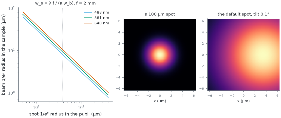
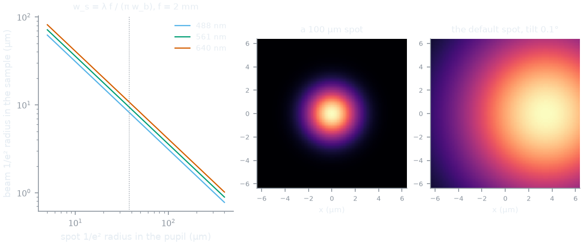
0 0 100 0 0 1 0 0 0 0 0 -- a 100 µm spot -- lights only a 4.1 µm beam in the centre of the field. Right: the default spot entering the pupil 0.1° off axis (tiltX 0.1) lands its envelope f tan(0.1°) = 3.5 µm off centre.
How this figure was made (3 cli runs, 27 ms)
Generated by tools/build_physics_figures.py (figure sim-spot) from the code it documents at commit 72b1b0f, on Linux with 4 threads, 2026-11-01. Commands, in order, with their wall time (those marked [served] ran one after the other in one insiliscope_cli --serve process, which keeps the world and the PSF kernel between commands; their outputs are the same as separate runs'):
insiliscope_cli --setup-json spot0.setup.json --x 6.58 --y -5.61 --size 128 --frames 1 --mt-mode WideField --mt-dye -1 --light-preset auto --illum-bfp 0 --npc-dye None    # 11 ms [served]
insiliscope_cli --setup-json spot100.setup.json --x 6.58 --y -5.61 --size 128 --frames 1 --mt-mode WideField --mt-dye -1 --light-preset auto --illum-bfp 0 --sim-beams 0 0 100 0 0 1 0 0 0 0 0 --npc-dye None    # 8.0 ms [served]
insiliscope_cli --setup-json tilt.setup.json --x 6.58 --y -5.61 --size 128 --frames 1 --mt-mode WideField --mt-dye -1 --light-preset auto --illum-bfp 0 --sim-beams 0 0 0 0.1 0 1 0 0 0 0 0 --npc-dye None    # 7.6 ms [served]
The frame program. Frame f of the sample's frame sequence takes the phase index f mod nPhases and the orientation
index f / nPhases (every phase of an orientation, then the next; sim-order PhaseMajor swaps them); the orientation
rotates every beam by 180° / sim-angles, the phase adds phaseStep × phase / nPhases turns to each beam. A cli stack
starts at frame 0 and writes the state per frame to <out>.pattern.csv; the viewer's live sample counts its frames
(every frame, dark ones too; a fresh sample starts at 0). A phase drift (Expert) makes each beam's phase walk per frame
(sim-phase-drift-turns-per-sqrt-sec) or slide (sim-phase-drift-turns-per-sec).
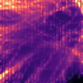
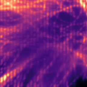
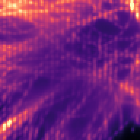
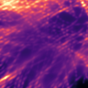
| frame 0 (angle 0, phase 0) | frame 1 (phase 1) | frame 2 (phase 2) | frame 3 (angle 1) | the 9 frames summed | 2 x 9 x one beam |
|---|---|---|---|---|---|
 |
 |
 |
 |
 |
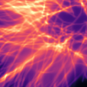 |
The photon images (before the camera) of a 2D SIM cycle on the widefield microtubules (mEGFP, 488 nm, the beams at 0.5): the fringe moves by a third of its period per frame and turns by 60° every three frames. Summed over the cycle the fringes cancel: the sum equals twice nine frames under the single beam at the same power (the pair carries two beams), per pixel 0.274 ± 0.081 over the lit field -- the cycle mean the dyes' kinetics run on.
How this figure was made (2 cli runs, 4.40 s)
Generated by tools/build_physics_figures.py (figure sim-cycle) from the code it documents at commit 72b1b0f, on Linux with 4 threads, 2026-11-01. Commands, in order, with their wall time (those marked [served] ran one after the other in one insiliscope_cli --serve process, which keeps the world and the PSF kernel between commands; their outputs are the same as separate runs'):
insiliscope_cli --out sim2d.movie.tif --photons-out sim2d.photons.tif --setup-json sim2d.setup.json --x 6.58 --y -5.61 --size 96 --frames 9 --mt-mode WideField --mt-dye -1 --light-preset auto --illum-bfp 0.5 --sim-type SIM2D --npc-dye None    # 4.20 s [served]
insiliscope_cli --out off.movie.tif --photons-out off.photons.tif --setup-json off.setup.json --x 6.58 --y -5.61 --size 96 --frames 9 --mt-mode WideField --mt-dye -1 --light-preset auto --illum-bfp 0.5 --npc-dye None    # 198 ms [served]
What the dyes see. The emission of every frame uses that frame's exact pattern: each blink's photons at its site,
the mean-field image under the pattern (one scene per pattern state), the background at the coverslip. One exception,
for speed: the blink modes' always-glowing dyes (dSTORM's initial ON, PALM's pre state) glow under the cycle mean,
one image as without a pattern (live dSTORM-SIM ~6x faster; over a full cycle the same photons, 1 % per pixel apart
in a 9-frame SIM2D test); Renderer.Quality Exhaustive (Renderer.PatternOnContinuousDyes On, Expert;
--sim-frame-pattern-continuous 1) gives them the frame's pattern too. The blinks and WideField dyes always take it.
The kinetics
(dSTORM switching, PALM activation, bleaching, the background fade) run on the cycle mean of the pattern, the
beams' incoherent sum, which the pattern summed over a full phase cycle equals exactly: a dye's dose within a cycle is
off by at most one frame's modulation, and the light history keeps one chapter per beam set (one component per beam
of the cycle) instead of a fringe it could not resolve. The DNA-PAINT imager background uses the cycle mean too (the
defocused column blurs the fringes). A fiducial bead takes the pattern averaged over its
volume (the ball's form factor per fringe term: a 200 nm bead on a 200 nm fringe keeps about a third of the modulation,
and is never dark), and the fluorescent slide shows the frame's fringes imaged through the PSF
at every height's defocus: in a thick layer only the heights near focus keep their fringe, so its contrast is a
fraction of the pattern's; a thin layer or TIRF-SIM shows it in full.
The DNA-PAINT imager background
Unbound imager in the illuminated volume adds an offset per pixel and second of
with \(c\) the imager concentration, \(H\) the chamber height (chamber-height-um, default 100 µm, an estimate:
tape and flow chambers), \(A_{px}\) the pixel area in the sample, \(e\) the excitation factor of the illumination
geometry (illum-bfp) and \(K\) the spread of a dye's light at a distance \(|z - z_f|\) from the focal plane: the
light of the imager high above the focus lands on the camera defocused, spread over a disc of radius
\(|z - z_f| \tan\theta\), so a pixel collects the lit imager within that reach of it, not the column above it alone.
\(K\) is geometric optics in one medium: an isotropic emitter (a freely rotating imager), its emission angles weighted by
the Fresnel power transmittance into the coverslip (Born & Wolf 1999, section 1.5.3; s and p averaged), collected with
equal power per solid angle by an aplanatic objective (Richards & Wolf 1959) up to its NA. Without the weighting the
focal-plane irradiance of a dye at defocus \(\delta\) is \(\delta / 2\pi(\delta^2 + r^2)^{3/2}\), and on the axis of a
lit disc of radius \(a\) the column is \(\int_0^H 1 - \delta/\sqrt{a^2 + \delta^2}\,d\delta \approx a\) for
\(H \gg a\); the Fresnel weighting favours the steep rays, so the effective column is a little deeper.
So in epi the background is set by the beam's width, not the chamber's height: about 15 µm on the axis of the
default beam, a Gaussian of 25.6 µm FWHM (14 µm with a FlatTop that wide; 100 µm before this model), and about half
that at the beam's edge. In TIRF only the
evanescent layer is lit (about the field factor times the decay depth, ~0.5 µm), in HILO about the inclined sheet. That
is why DNA-PAINT is imaged in HILO or TIRF: the DNA-PAINT light presets set HILO (illum-bfp 0.95), the nanorulers TIRF
(1.03), both estimates; TIRF cuts the nanorulers' imager background about 13-fold against epi. The renderers evaluate
it on a node grid (a third of the beam's edge width apart) and interpolate: within 0.2 % of a dense quadrature in epi
and TIRF, 2 % in HILO. The map depends on the focus (the defocus of each height; HILO's sheet pivots at the focus), so
it is made at foci 0.25 µm apart and blended linearly between the two around the focus: a focus move reuses them, and
Micro-Manager makes the neighbouring ones ahead on a worker thread. A Flat beam (laterally infinite) lights every plane
alike, so the spread changes nothing: there the column is the plain integral, \(H\) in epi.
Left out: the index mismatch between the medium and the glass (the defocus is taken in one medium), the dye's emission dipole (a free imager rotates: isotropic), the near-field (supercritical-angle) emission of dyes within a wavelength of the coverslip, imager depletion and its exclusion from the cells: the background is the same over cells and medium and does not drop as imager binds.
The background against the imager concentration, the model next to the rendered photons:
| Imager | 0.3 nM | 1 nM | 3 nM | 10 nM |
|---|---|---|---|---|
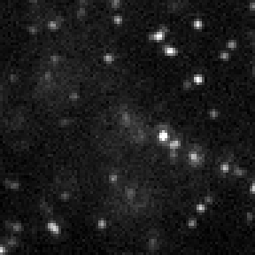
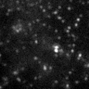
| Frame | 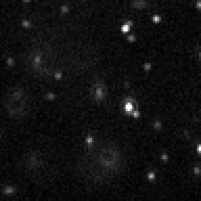 |
 |
 |
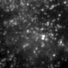 |
| Background, model (photons/px/frame) | 17.9 | 59.7 | 179 | 597 |
| Median, rendered (photons/px/frame) | 22.0 | 74.4 | 232 | 798 |
The DNA-PAINT imager concentration sets the binding rate (konc: more blinks) and the free imager's flat background c NA H Apx kemηF (model row, from the cli's setup output), here under a laterally infinite flat epi beam and a 5 um chamber (H), where the column is the chamber's height; under a shaped beam the collected column is about the beam's radius (above). The rendered row is the median of the photon images before the camera, which also holds the blinks' halos. Frames: one camera frame (ADU, each its own contrast). Default 1 nM; frames 50 ms.
How this figure was made (4 cli runs, 2.65 s)
Generated by tools/build_physics_figures.py (figure light-imager) from the code it documents at commit 72b1b0f, on Linux with 4 threads, 2026-11-01. Commands, in order, with their wall time (those marked [served] ran one after the other in one insiliscope_cli --serve process, which keeps the world and the PSF kernel between commands; their outputs are the same as separate runs'):
insiliscope_cli --out c0.3.movie.tif --photons-out c0.3.photons.tif --setup-json c0.3.setup.json --x 6.58 --y -5.61 --size 96 --frames 5 --mt-imager-nm 0.3 --illum-profile Flat --illum-bfp 0 --chamber-height-um 5 --npc-dye None    # 1.18 s [served]
insiliscope_cli --out c1.movie.tif --photons-out c1.photons.tif --setup-json c1.setup.json --x 6.58 --y -5.61 --size 96 --frames 5 --mt-imager-nm 1 --illum-profile Flat --illum-bfp 0 --chamber-height-um 5 --npc-dye None    # 273 ms [served]
insiliscope_cli --out c3.movie.tif --photons-out c3.photons.tif --setup-json c3.setup.json --x 6.58 --y -5.61 --size 96 --frames 5 --mt-imager-nm 3 --illum-profile Flat --illum-bfp 0 --chamber-height-um 5 --npc-dye None    # 533 ms [served]
insiliscope_cli --out c10.movie.tif --photons-out c10.photons.tif --setup-json c10.setup.json --x 6.58 --y -5.61 --size 96 --frames 5 --mt-imager-nm 10 --illum-profile Flat --illum-bfp 0 --chamber-height-um 5 --npc-dye None    # 668 ms [served]
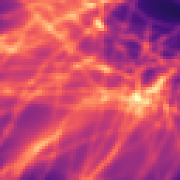
Continuous populations: mean field or per dye
Pre states, the dSTORM initial ON and WideField-mode dyes emit continuously. Such a population renders either
- mean field: the structure's dye density binned on world-anchored z planes (
wf-plane-nm) on a grid (wf-upscalecells per pixel, spanning the FOV plus a 2 µm margin), convolved with the state's PSF, times the exact mean photons per dye of the frame, \(r\,(e^{-\lambda t_0} - e^{-\lambda t_1})/\lambda\) (under a shaped beam with each place's own dose and rate); or - per dye: each dye's window (its own address-based end: bleached at aux \(\times\) budget / \(k_{em}\), activated, or the initial ON's end) splatted as a unit image into a running image that changes only where windows start or end.
The switch is per frame: mean field while the expected emitters exceed mean-field-density-per-um2 (default 20) in the
mean-field-slab-nm (500 nm) slab around focus, or mean-field-max-emitters (5000) in the z range; per dye below
(MM Renderer.MeanField*). Both give the same mean (checked within 1 % in total, a few % per pixel).
One population rendered both ways:
| Per dye | Mean field | Mean field - per dye | |
|---|---|---|---|
| Photons | 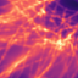 |
 |
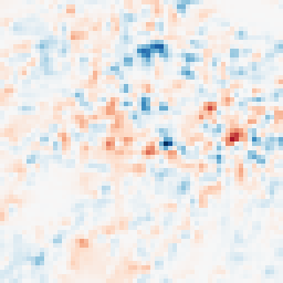 |
| How | Each dye's window splatted | Dye density on z planes × PSF | ±43 photons = 31 % of the mean |
| Total photons | 5.704×10⁵ | 5.697×10⁵ | -0.13 % |
| rms difference per pixel | 4.5 % of the mean | ||
| Setup / frame | 649 ms / 407 ms | 420 ms / 70 µs |
A continuous population (mEGFP WideField, 10 % of the sites labelled, 64 px, 50 ms frames; the images are the first frame) rendered both ways, forced by the switch's thresholds; by default the renderer picks mean field above 20 emitting dyes per µm2 of the 500 nm focal slab (mean-field-density-per-um2). Times on the build machine (4 threads): the setup in a fresh process, the frame time averaged over 20 frames.
How this figure was made (2 cli runs, 9.29 s)
Generated by tools/build_physics_figures.py (figure light-meanfield) from the code it documents at commit 72b1b0f, on Linux with 4 threads, 2026-11-01. Commands, in order, with their wall time:
insiliscope_cli --photons-out meanfield.photons.tif --x 6.58 --y -5.61 --size 64 --frames 20 --mt-mode WideField --mt-dye -1 --light-preset auto --mt-label-pct 10 --mean-field-density-per-um2 0 --npc-dye None    # 451 ms
insiliscope_cli --photons-out perdye.photons.tif --x 6.58 --y -5.61 --size 64 --frames 20 --mt-mode WideField --mt-dye -1 --light-preset auto --mt-label-pct 10 --mean-field-density-per-um2 1000000000000 --mean-field-max-emitters 1000000000000 --npc-dye None    # 8.84 s
Blinks: splat, binned or mean field
The blinks of dSTORM, PALM and DNA-PAINT render in one of three regimes, chosen per label and per frame:
| Regime | What is drawn | Exact | Lost |
|---|---|---|---|
| SMLM (splat) | every blink, its PSF splatted at its position | everything | -- |
| Binned (approximate SMLM) | the same blinks, each snapped to a grid of blink-binned-upscale cells per pixel, one density per PSF z plane, FFT-convolved with that plane's kernel |
which dyes blink, their photons and z plane, the frame-to-frame fluctuation | the position within a cell (±half a cell, ±25 nm at the default 2 cells per 100 nm pixel) |
| Mean field | no blinks: each dye's expected ON time in the frame times the dye density, convolved once | the mean image | the blinking itself |
- Splat or binned. The splat costs per blink, the binned FFT per field-of-view area. A frame renders binned while
more than
blink-binned-density-per-um2(default 12.5; MMRenderer.BlinkBinnedDensityPerUm2) blinks are ON per µm² of the field of view, orblink-binned-max-emitters(1e9) in all; splatted below. The default is an estimate, measured on this implementation (the splat/binned break-even is ~10 per µm²; 12.5 sits just above it): 256 px × 100 frames of DNA-PAINT took 2.9 / 22.9 / 240 s splatted at 1 / 10 / 100 nM imager and 13–20 s binned at any density (upscale 2; 3–4 s at upscale 1). Binned against splat, same blinks: the photons agree within 0.1 %, the mean image within 0.5–2 % (relative L2). - Mean field is decided before any blink is drawn, from the expected ON emitters: above
blink-mean-field-density-per-um2per µm² of themean-field-slab-nmslab, orblink-mean-field-max-emittersin the z range. A movie that is mean-field throughout draws no blinks at all. The expected ON time is closed form: dSTORM and PALM follow the dye's chain (initial ON → first dark → ON → bleached | OFF → ON) as a matrix exponential through each piece of the light history; DNA-PAINT integrates its 1 s binding bins exactly. It matches the core's own blinks to within 0.2 % (some 10^5 to 10^7 dyes). - Mean field is off by default (both thresholds 1e9), on purpose. For continuous emitters the mean image is exact up to shot noise. For blinks it is not: the blink fluctuation has a variance of about (photons per blink) times the shot-noise variance, and that fluctuation is the SMLM signal. A blink-mean-field movie has the right total signal (within 0.1 %), but its frame-to-frame noise is shot noise only (std 41 against 126 ADU in the check). Use it as a fast picture of where a dense label sits, not as SMLM data.
- The regime can change both ways within a movie (a power step, a 405 nm pulse). The progress line says which one drew
a frame:
SMLM: N blinks (splat),(binned FFT), orblinks: mean-field (FFT).
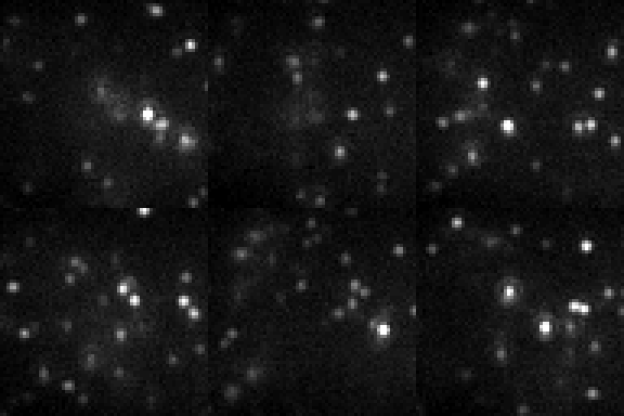
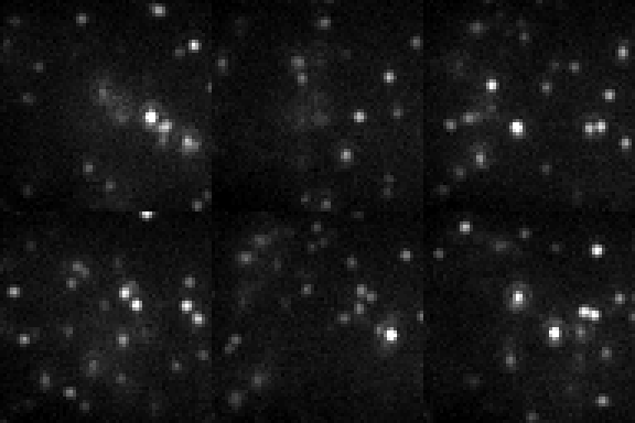
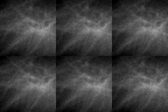
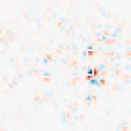
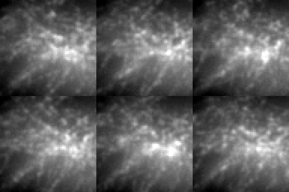
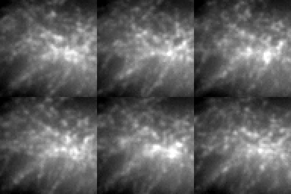
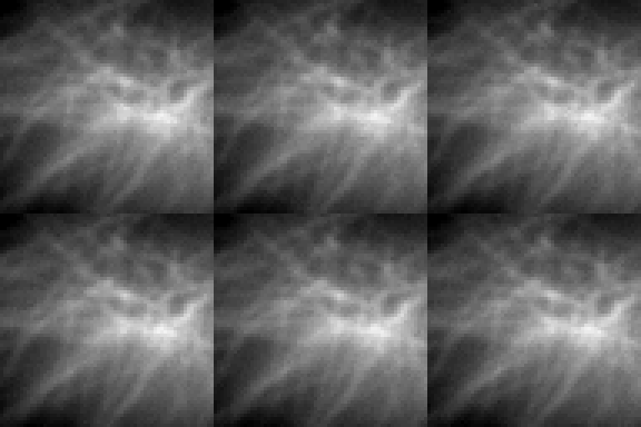
The three regimes at a low, medium and high imager concentration:
| Splat (SMLM) | Binned (approximate SMLM) | Mean field | Binned − splat (frame 0) | |
|---|---|---|---|---|
| Low: 1 nM imager 1.4 ON / µm2 (all z) 0.28 ON / µm2 in the focal slab default: splat |
 |
 |
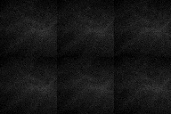 |
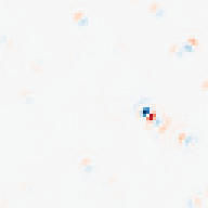 |
| 4.4 ms / frame photons +0.0 % frame-to-frame std 37 % of the mean |
17 ms / frame photons +0.1 % frame-to-frame std 37 % of the mean |
255 µs / frame photons -2.2 % frame-to-frame std 0 % of the mean |
±131 photons = 15 % of the splat frame's peak rms 8.8 % of its mean |
|
| Medium: 10 nM imager 13 ON / µm2 (all z) 2.8 ON / µm2 in the focal slab default: binned |
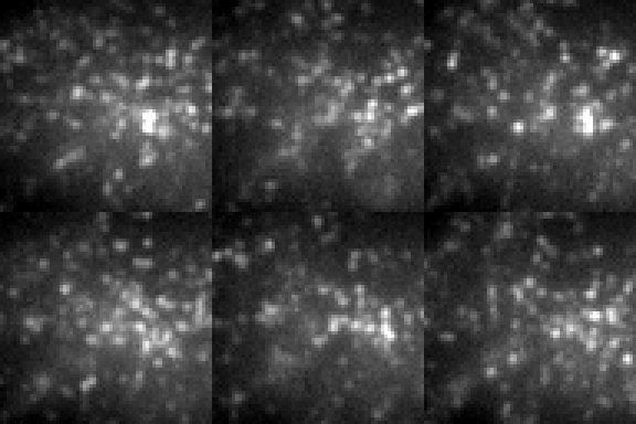 |
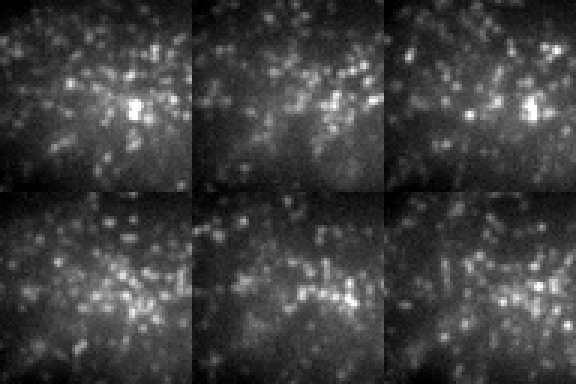 |
 |
 |
| 39 ms / frame photons +0.0 % frame-to-frame std 14 % of the mean |
20 ms / frame photons +0.1 % frame-to-frame std 14 % of the mean |
165 µs / frame photons -0.7 % frame-to-frame std 0 % of the mean |
±194 photons = 7.7 % of the splat frame's peak rms 2.5 % of its mean |
|
| High: 100 nM imager 133 ON / µm2 (all z) 28 ON / µm2 in the focal slab default: binned |
 |
 |
 |
 |
| 308 ms / frame photons +0.0 % frame-to-frame std 4.6 % of the mean |
21 ms / frame photons +0.1 % frame-to-frame std 4.6 % of the mean |
165 µs / frame photons +0.0 % frame-to-frame std 0 % of the mean |
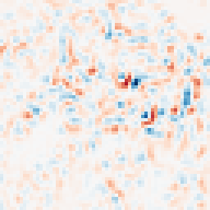
±314 photons = 2.9 % of the splat frame's peak rms 0.76 % of its mean |
DNA-PAINT (ATTO 655 imager, 64 px, 20 frames of 50 ms) at three imager concentrations, each rendered in the three blink regimes, forced by their thresholds (one movie per cell, camera ADU on one scale per row). Splat and binned draw the same blinks; binned snaps each to a cell of half a pixel (±25 nm), and the last column is what that moves: the photon images (before the camera's noise) of frame 0, binned minus splat, red where binned has more light, blue where less, on ± the largest difference. Mean field draws no blinks, only each dye's expected ON time, so its frames hold still apart from shot noise.
ON / µm2: the ON emitters per frame (each blink weighted by the part of the frame it is ON) per µm2 of the field of view, over all depths and within the 500 nm focal slab (mean-field-slab-nm), averaged over the movie. default is the regime the renderer picks by itself: binned while more than 12.5 are ON per µm2 of the field of view (blink-binned-density-per-um2; the rule counts the blinks the movie queries, which reach a little beyond the field of view), splat below. Mean field is never picked by default: it takes over only when you set blink-mean-field-density-per-um2 below the expected ON density in the focal slab (or blink-mean-field-max-emitters below the expected ON count over all depths); both are 1e9 by default, because mean field loses the blinking. Photons: the movie's total against the splat's; frame-to-frame std: of the photon images, per pixel, averaged (0 for mean field, whose expected image stays put). Times on the build machine (4 threads), per frame.
How this figure was made (15 cli runs, 24.7 s)
Generated by tools/build_physics_figures.py (figure light-blink-regimes) from the code it documents at commit 72b1b0f, on Linux with 4 threads, 2026-11-01. Commands, in order, with their wall time (those marked [served] ran one after the other in one insiliscope_cli --serve process, which keeps the world and the PSF kernel between commands; their outputs are the same as separate runs'):
insiliscope_cli --out 1nM-splat.movie.tif --photons-out 1nM-splat.photons.tif --setup-json 1nM-splat.setup.json --x 6.58 --y -5.61 --size 64 --frames 20 --mt-mode DNA-PAINT --mt-dye -1 --light-preset auto --mt-imager-nm 1 --blink-binned-density-per-um2 1000000000 --npc-dye None    # 1.66 s [served]
insiliscope_cli --out 1nM-binned.movie.tif --photons-out 1nM-binned.photons.tif --setup-json 1nM-binned.setup.json --x 6.58 --y -5.61 --size 64 --frames 20 --mt-mode DNA-PAINT --mt-dye -1 --light-preset auto --mt-imager-nm 1 --blink-binned-max-emitters 0 --npc-dye None    # 781 ms [served]
insiliscope_cli --out 1nM-mean.movie.tif --photons-out 1nM-mean.photons.tif --setup-json 1nM-mean.setup.json --x 6.58 --y -5.61 --size 64 --frames 20 --mt-mode DNA-PAINT --mt-dye -1 --light-preset auto --mt-imager-nm 1 --blink-mean-field-max-emitters 0 --npc-dye None    # 227 ms [served]
insiliscope_cli --dyes-json 1nM-dyes.dyes.json --x 6.58 --y -5.61 --size 64 --frames 20 --mt-mode DNA-PAINT --mt-dye -1 --light-preset auto --mt-imager-nm 1 --dyes-t 60,61 --npc-dye None    # 1.39 s [served]
insiliscope_cli --photons-out 1nM-default.photons.tif --x 6.58 --y -5.61 --size 64 --frames 20 --mt-mode DNA-PAINT --mt-dye -1 --light-preset auto --mt-imager-nm 1 --npc-dye None    # 85 ms [served]
insiliscope_cli --out 10nM-splat.movie.tif --photons-out 10nM-splat.photons.tif --setup-json 10nM-splat.setup.json --x 6.58 --y -5.61 --size 64 --frames 20 --mt-mode DNA-PAINT --mt-dye -1 --light-preset auto --mt-imager-nm 10 --blink-binned-density-per-um2 1000000000 --npc-dye None    # 1.66 s [served]
insiliscope_cli --out 10nM-binned.movie.tif --photons-out 10nM-binned.photons.tif --setup-json 10nM-binned.setup.json --x 6.58 --y -5.61 --size 64 --frames 20 --mt-mode DNA-PAINT --mt-dye -1 --light-preset auto --mt-imager-nm 10 --blink-binned-max-emitters 0 --npc-dye None    # 816 ms [served]
insiliscope_cli --out 10nM-mean.movie.tif --photons-out 10nM-mean.photons.tif --setup-json 10nM-mean.setup.json --x 6.58 --y -5.61 --size 64 --frames 20 --mt-mode DNA-PAINT --mt-dye -1 --light-preset auto --mt-imager-nm 10 --blink-mean-field-max-emitters 0 --npc-dye None    # 160 ms [served]
insiliscope_cli --dyes-json 10nM-dyes.dyes.json --x 6.58 --y -5.61 --size 64 --frames 20 --mt-mode DNA-PAINT --mt-dye -1 --light-preset auto --mt-imager-nm 10 --dyes-t 60,61 --npc-dye None    # 1.38 s [served]
insiliscope_cli --photons-out 10nM-default.photons.tif --x 6.58 --y -5.61 --size 64 --frames 20 --mt-mode DNA-PAINT --mt-dye -1 --light-preset auto --mt-imager-nm 10 --npc-dye None    # 405 ms [served]
insiliscope_cli --out 100nM-splat.movie.tif --photons-out 100nM-splat.photons.tif --setup-json 100nM-splat.setup.json --x 6.58 --y -5.61 --size 64 --frames 20 --mt-mode DNA-PAINT --mt-dye -1 --light-preset auto --mt-imager-nm 100 --blink-binned-density-per-um2 1000000000 --npc-dye None    # 12.9 s [served]
insiliscope_cli --out 100nM-binned.movie.tif --photons-out 100nM-binned.photons.tif --setup-json 100nM-binned.setup.json --x 6.58 --y -5.61 --size 64 --frames 20 --mt-mode DNA-PAINT --mt-dye -1 --light-preset auto --mt-imager-nm 100 --blink-binned-max-emitters 0 --npc-dye None    # 915 ms [served]
insiliscope_cli --out 100nM-mean.movie.tif --photons-out 100nM-mean.photons.tif --setup-json 100nM-mean.setup.json --x 6.58 --y -5.61 --size 64 --frames 20 --mt-mode DNA-PAINT --mt-dye -1 --light-preset auto --mt-imager-nm 100 --blink-mean-field-max-emitters 0 --npc-dye None    # 159 ms [served]
insiliscope_cli --dyes-json 100nM-dyes.dyes.json --x 6.58 --y -5.61 --size 64 --frames 20 --mt-mode DNA-PAINT --mt-dye -1 --light-preset auto --mt-imager-nm 100 --dyes-t 60,61 --npc-dye None    # 1.68 s [served]
insiliscope_cli --photons-out 100nM-default.photons.tif --x 6.58 --y -5.61 --size 64 --frames 20 --mt-mode DNA-PAINT --mt-dye -1 --light-preset auto --mt-imager-nm 100 --npc-dye None    # 482 ms [served]
Where it lives
adapter/inSiliScope/Simulation/Spectra.*, LightPath.*, DyeLibrary.* (data generated into DyeLibraryData.inc by
tools/gen_dye_library.mjs), ScopeMovie.* (FluorescenceMovie), BinnedBlinks.* and BlinkExpectation.*. The core's label model (ABI 10) is in
core/src/dyes.*; spec/PORT.md section 16 has the details.